The liquid boundary conditions are overdetermined when too many parameters are prescribed, which are at least numerically competing. For example, if discharge and water depth are prescribed but cannot be achieved with the defined roughness coefficients, Telemac will attempt to comply with the water depth. However, this water depth does often not correspond to the prescribed discharge and Telemac tries to compensate for the difference by varying the lengths (amounts) of the velocity vectors. In turn, the velocity vectors are constrained by the roughness coefficients. Thus, Telemac tries to vary water depths and velocity vectors to achieve a stage (H)-discharge (Q) relation prescribed at the boundary, which might be impossible with the defined roughness. A workaround would be to adjust roughness (friction) coefficients so that the defined boundary conditions and roughness coefficients are exactly in balance. However, the boundary conditions should be calibrated specifically for multiple terrain types (i.e., roughness zones) through model calibration using measured values and not imposed by issues at the model boundaries to achieve mass balance. So, what next?
Um das Problem der überdeterminierten Randbedingungen und des Massenungleichgewichts zu lösen, geben die nächsten Abschnitte zuerst Tipps zum richtigen geometrischen Platzieren von Flüssigkeitsgrenzen und erinnern dann an die Einrichtung einer Grenzdatei, die Arten von Grenzen (d. H. Werte) und wie sie die Massenbilanz beeinflussen könnten.
Flüssige Grenzen zeichnen
Beim Zeichnen von Flüssigkeitsgrenzen, zum Beispiel in BlueKenue, helfen einige geometrische Eigenschaften, die Stabilität und Massenbilanz der späteren Simulation zu verbessern:
Flüssigkeitsgrenzen sollten mindestens 5-10 Knoten haben.
Alle Flüssigkeitszuflussgrenzen sollten eine nahezu gleiche Anzahl von Knoten haben wie die Summe der Flüssigkeitsabflussgrenzen.
Liquid inflow (upstream) boundaries should only be defined at the lower riverbed, never on the riverbanks or floodplains (see Fig. 1).
Ziehen Sie die Grenzen ausreichend weit weg von der Region von Interesse: auferlegte oder unrealistische Wassertiefen (oder Wasseroberflächenerhöhungen) im Zusammenhang mit den Durchflussraten werden ansonsten die Region von Interesse stark beeinflussen. Als Faustregel gilt, dass in einer 2D-Simulation die stromaufwärts gelegenen und stromabwärts gelegenen Grenzen mindestens 800 bis 1000 m von der interessierenden Region entfernt sein sollten.
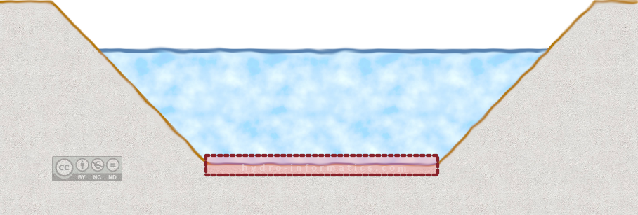
Figure 1:Der rot hervorgehobene Teil dieses qualitativen Querschnitts sollte als Zufluss- (vorgelagerte) Randbedingung definiert werden. Mesh-Knoten an den Flussufern und auf den Auen sollten nicht enthalten sein.
Die Struktur der Grenzen.cli
Die stetigen 2d, instationären 2d und Tutorials zeigen die verschiedenen Arten von Grenzen mit vorgeschriebener Entladung (Q) und / oder Wassertiefe (H), die in eine Borders .cli Datei implementiert werden, die aus 13 Leerzeichen (Tab) besteht - getrennte Doppelpunkte:
The 13 space (tab) - separated colons correspond to 13 boundary variables, which are listed in Table 1 for a hydrodynamic Telemac2d/3d (see boundaries.cli) and a Gaia boundary conditions file.
Table 1:Meaning of columns in a Boundary.Cli file for Telemac2d/3d and Gaia.
Spalte Nr. | Flag | Telemac2d/3d | Gaia |
|---|---|---|---|
1 | Grenztyp | LIHBOR | LIHBOR |
2 | Grenztyp | LIUBOR | LIQBOR |
3 | Grenztyp | LIVBOR | LIVBOR |
4 | Verschreibung | HBOR | Q2BOR |
5 | Verschreibung | UBOR | UBOR |
6 | Verschreibung | VBOR | VBOR |
7 | Verschreibung | AUBOR | AUBOR |
8 | Grenztyp | LITBOR | LIEBOR (LICBOR) |
9 | Verschreibung | TBOR | EBOR (CBOR) |
10 | Verschreibung | ATBOR | ATBOR |
11 | Verschreibung | BTBOR | BTBOR |
12 | Global Node ID | N | N |
13 | Lokale Knoten-ID | K boundary file | K boundary file |
The first three columns of a .cli file determine whether a boundary is solid or liquid, and if liquid, the type of liquid boundaries. These three columns (i.e. LIHBOR, LIUBOR, and LIVBOR) may take the following values:
0to enforce a zero velocity boundary2to indicate a solid (wall) boundary with friction4to define a free liquid boundary type5to define a prescribed (i.e., determined) liquid boundary type6um eine Geschwindigkeit vorzuschreiben (nur für LIUBOR/LIVBOR)
Also, these values can be assigned to column 8 (LITBOR/LIEBOR) of the .cli file. Note that in a hydrodynamic simulation, the combination of columns 2 and 3 (LIUBOR and LIVBOR) is effectively a discharge boundary. All other columns are Prescriptions and Node IDs. The Prescriptions may be used to impose, for example, a flow velocity value (not recommended). The Node IDs were written by BlueKenue (or whatever mesh generator was used) and should not be modified. Thus, regarding the mass balance of water, the first three columns are important and they can get assigned the (common) value combinations listed in Tab. 2 below. For the mass balance of tracers, column 8 can be defined analogously. Additionally, a .cli file for sediment transport can be similarly defined with the first three columns, as described in the Gaia tutorial.
Table 2:Value combinations for the first three columns of a hydrodynamic boundaries.cli file affecting the mass balance of water.
Typ | Nummercode | Typische Anwendung |
|---|---|---|
Festkörper |
| Feste Grenzen |
Vorgeschriebenes Q |
| |
Vorgeschrieben H |
| |
Vorgeschriebenes H und Q |
| Stream gauges (eher vermeiden) |
Bearbeiten Sie limit.cli, um die Bedingungen zu ändern
To view or edit the type of boundary conditions, open the .cli file with a text editor (read more about text editors). Typically, most of the rows will hold the value combination 2 2 2 in columns 1-3, that is, they are solid boundaries. The liquid boundary rows start with 4 or 5 as listed in Tab. 2. Every row in the .cli file represents a node of the mesh, and neighboring rows represent neighboring mesh nodes. For instance, the node described in row (line) 435 of a .cli file is geospatially located directly between the boundary nodes described in lines 434 and 436 of the .cli file. Since the definitions in the .cli file are purely geometric or geometric attributes, additional hydraulic attributes must be prescribed or linked in the steering (.cas) file. Thus, the Telemac steering file controls how much water is flowing through the liquid boundaries, and/or the water depth/surface elevation with the following keywords:
/ Keywords in a .cas steering file
PRESCRIBED ELEVATIONS : 518.20 ; 0
PRESCRIBED FLOWRATES  : 0 ; 118.0
/ PRESCRIBED VELOCITIES : 1.0 ; 1.0 / not use simultaneously with PRESCRIBED FLOWRATES
/ PRESCRIBED DEPTH : 1.0 ; 1.0 / not use simultaneously with PRESCRIBED ELEVATIONS
Alternative usages of these keywords can be found in the unsteady 2d and Gaia tutorials, or section 4.2 of the Telemac2d manual. Note that every PRESCRIBED ... row separates values for each liquid boundary with a ; sign. Notably, the first and second values apply to the first and second boundaries defined in the .cli file, counting from the top of the .cli file (see next paragraph). If one of these values is 0 (e.g., the second ELEVATION and the first FLOWRATE boundary), Telemac will treat it as a free (4) liquid boundary.
The order of boundaries can be found in the .cli file: the first node sequence where rows (lines) start with either 4 or 5 (or 6) is the first liquid boundary. Because the mesh generator placed neighboring nodes in neighboring rows, the boundary lines are defined in neighboring rows, too. The below box features an example of a downstream boundary defined between nodes 7-12 (global IDs 144-9818). Further down in the .cli file, another liquid boundary (e.g., 4 5 5) might be found to define upstream inflows. In this case, the downstream boundary is boundary 1 and the upstream boundary is boundary 2, and both are accordingly prescribed in the steering (.cas) file.
Grenzen und Konvergenz
Die Verschreibung von 5 4 4 (nur H), 4 5 5 (nur Q) oder 5 5 5 (Q und H) Randbedingungen in above example kann zu numerischen Instabilitäten einer trocken initialisierten Simulation oder zu unausgewogenen Zu- und Abflüssen führen.
To verify mass conservation, refer to the next section on quantitative convergence analysis of fluxes across (or through) the liquid boundaries.
To troubleshoot mass convergence issues, have a look at our workflow for mass conservation.