The mesh is an essential part of the numerical solution and must meet certain criteria in order to generate a valid and precise solution. The following section describes the snappyHexMesh utility for creating 3d meshes containing hexahedral and split-hexahedral cells from triangulated surface geometries.
Further details regarding the mesh specification and validity constraints can be found in Chapter 4 of the OpenFOAM User Guide. In order to run snappyHexMesh, in addition to an existing geometry base mesh, the following files are required:
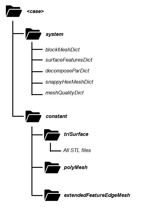
Figure 1:Case directory containing the files necessary to run snappyHexMesh.
The following sections describe the steps that need to be followed.
Creation of the Background Hex Mesh
Before being able to run snappyHexMesh, a background mesh characterized by hexahedral cells has to be created. This mesh needs to contain the entire region that should be meshed with snappyHexMesh, as shown in the figure below.
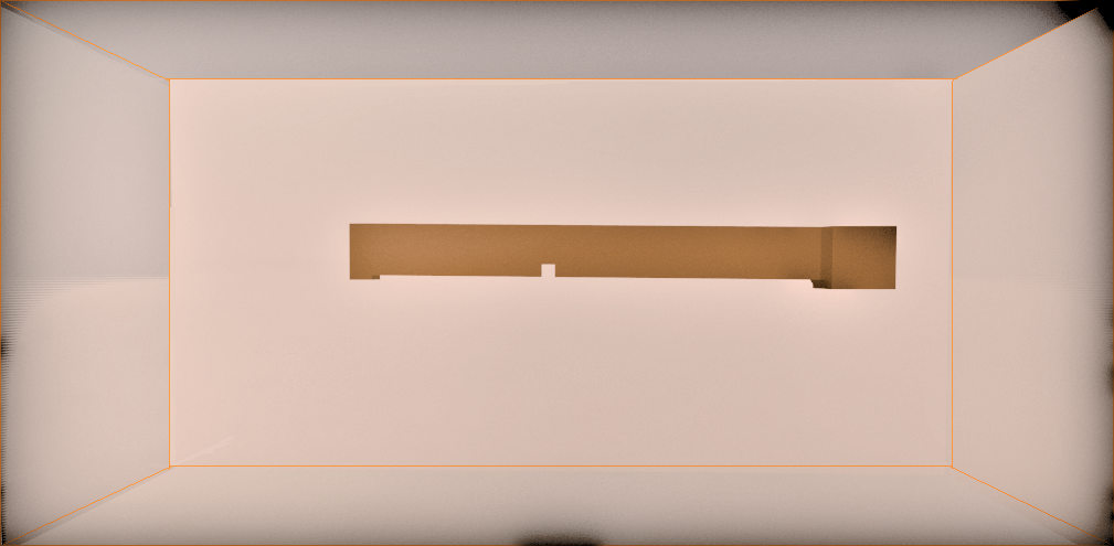
Figure 2:Background mesh created with blockMesh containing the structure to be meshed.
In the blockMeshDict file, the following items need to be added:
the scaling factor for the vertex coordinates
convertToMeters 1;coordinates of the vertices of the background mesh
    vertices
        (
            ( -30.0 -25.0 -25.0 )   //vertex number 0
            ( 70.0 -25.0 -25.0 )   //vertex number 1
            ( 70.0 25.0 -25.0 )   //vertex number 2
            ( -30.0 25.0 -25.0 )   //vertex number 3
            ( -30.0 -25.0 25.0 )   //vertex number 4
            ( 70.0 -25.0 25.0 )   //vertex number 5
            ( 70.0 25.0 25.0 )   //vertex number 6
            ( -30.0 25.0 25.0 )   //vertex number 7
        );
coordinates of the vertices, following the order indicated below
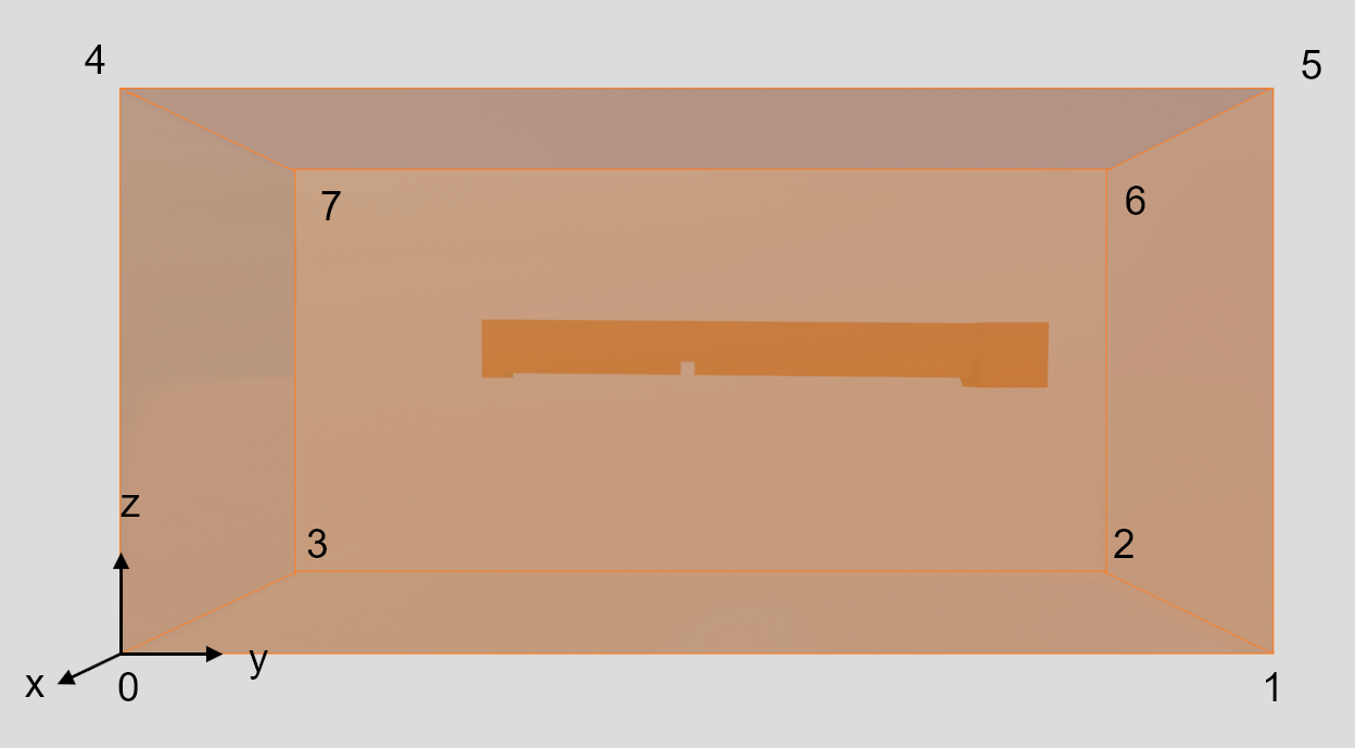
Figure 3:Background mesh indicating the order in which the vertices are written in the block-meshDict file.
an ordered list of vertex labels and mesh size
    blocks
        (
            hex (0 1 2 3 4 5 6 7)   // vertex numbers
            (400 200 200)   // number of cells in each direction
            simpleGrading (1 1 1) // cell expansion ratios
        );
For further details regarding the blockMesh utility refer to blockMesh in the OpenFOAM User Guide.
SurfaceFeaturesDict
The surfaceFeaturesDict extracts and writes all surface features to a file. In this file, all the STL files that have been saved in the triSurface folder have to be added as follows:
    Air
    {
        surfaces
            ("Air.stl");
        includedAngle   180;

    // Write features to obj format for postprocessing
        writeObj                yes;
    }
The complete version of the surfaceFeaturesDict for the current tutorial is saved in the case folder.
decomposeParDict
The decomposeParDict is used to decompose a mesh and fields of a case for parallel execution. When running in parallel, the geometry has to first be segmented into individual geometries for each MPI (Message Passing Interface, a standard for parallel computing) process. The numberOfSubdomains entry is mandatory, and the Method defines the decomposition method type. Several decomposition methods are available. Therefore, the decomposeParDict file shown below presents only one exemplary option.
    numberOfSubdomains 8;
    method          simple;

    simpleCoeffs
    {
        n               (2 2 2);
        delta           0.001;
    }

    hierarchicalCoeffs
    {
        n               (1 1 1);
        delta           0.001;
        order           xyz;
    }

    manualCoeffs
    {
        dataFile        "";
    }

    distributed     no;

    roots           ( );
SnappyHexMesh
The snappyHexMeshDict dictionary contains a series of commands that control the various steps of the meshing process. The main ones are the following:
castellatedMesh enables the creation of a castellated (i.e., refined) mesh.
snap enables the surface snapping stage.
addLayers enables the surface layer insertion.
geometry is a sub-dictionary of all surface geometry used.
castellatedMeshControls is a sub-dictionary of controls for castellated mesh.
snapControls is a sub-dictionary of controls for surface snapping.
addLayersControls is a sub-dictionary of controls for layer addition.
meshQualityControls is a sub-dictionary of controls for mesh quality.
mergeTolerance is the merge tolerance as a fraction of the initial bounding mesh.
The key steps involved when running snappyHexMesh are:
Castellation: the cells that are beyond a region defined by a predefined point are removed.
Snapping: reconstructs the cells to move the edges from inside the region to the required boundary.
Layering: creates additional layers in the boundary region.
Mesh quality: control and verify the quality of the mesh.
For this example, the add Layers option, which enables the addition of viscous layers, was set to false.
/*--------------------------------*- C++ -*----------------------------------*\
| =========                 |                                                 |
| \\      /  F ield         | OpenFOAM: The Open Source CFD Toolbox           |
|  \\    /   O peration     | Version:  2.2.0                                 |
|   \\  /    A nd           | Web:      www.OpenFOAM.org                      |
|    \\/     M anipulation  |                                                 |
\*---------------------------------------------------------------------------*/
FoamFile
{
    format      ascii;
    class       dictionary;
    object      snappyHexMeshDict;
}
// * * * * * * * * * * * * * * * * * * * * * * * * * * * * * * * * * * * * * //

// Which of the steps to run
castellatedMesh true;    // make basic mesh
snap            true;    // decide to snap back to surface
addLayers       false;   // decide to add viscous layers
The GEOMETRY sub-dictionary lists all the surfaces used by snappyHexMeshDict, with the exception of the blockMesh geometry. Additionally, it defines a name for each of them to be used as a reference as shown in the example below.
geometry // Load all the STL files here
{
  Air.stl {type triSurfaceMesh; name Air;}
  Concrete-sides.stl {type triSurfaceMesh; name Concrete-sides;}
  Gravel-bottom.stl {type triSurfaceMesh; name Gravel-bottom;}
  Inlet.stl {type triSurfaceMesh; name Inlet;}
  Obstacle.stl {type triSurfaceMesh; name Obstacle;}
  Outlet.stl {type triSurfaceMesh; name Outlet;}
};
Castellation (Refinement)
The CastellatedMeshControls settings then allow the definition of the mesh refinement. The level of refinement can be set in the features, refinementSurfaces, and refinementRegions sections. Starting from level 0, which corresponds to no refinement, each subsequent refinement level divides the cell in 4 parts.
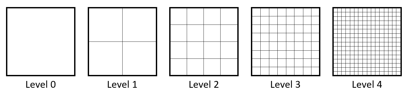
Figure 4:Example of different mesh refinement levels.
Additionally, the following items are set:
maxGlobalCells: defines the overall number of cells limit.
maxLocalCells: this setting is used in the case of parallel running, and defines the maximum number of cells for each processor.
nCellsBetweenLevels: avoids having sudden cell size changes, meaning consecutive refinement level changes close together.
For further details regarding these settings refer to the castellation and refinement section of the OpenFOAM User Guide.
castellatedMeshControls
{
    maxLocalCells 50000000;   // max cells per CPU core
    maxGlobalCells 500000000; // max cells to use before mesh deletion step
    minRefinementCells 0;     // was 0 - zero means no bad cells are allowed during refinement stages
    nCellsBetweenLevels 3;    // expansion factor between each high & low refinement zone

    // Explicit feature edge refinement
    // ~~~~~~~~~~~~~~~~~~~~~~~~~~~~~~~~

    features // taken from STL from each .eMesh file created by "SurfaceFeatureExtract" command
    (
      {file "Air.eMesh"; level 0;}
      {file "Concrete-sides.eMesh"; level 0;}
      {file "Gravel-bottom.eMesh"; level 0;}
      {file "Inlet.eMesh"; level 0;}
      {file "Obstacle.eMesh"; level 0;}
      {file "Outlet.eMesh"; level 0;}
    );

    // Surface based refinement
    // ~~~~~~~~~~~~~~~~~~~~~~~~

    refinementSurfaces // Surface-wise min and max refinement level
    {
      Air {level (0 0);}
      Concrete-sides {level (1 3);}
      Gravel-bottom {level (2 3);}
      Inlet {level (1 3);}
      Obstacle {level (3 3);}
      Outlet {level (2 3);}
    }

    resolveFeatureAngle 30;  // Resolve sharp angles // Default 30
    refinementRegions        // In descending levels of fineness
    allowFreeStandingZoneFaces true;
}
In the refinementSurfaces section shown in the example above, different refinement levels were set for each constituent element. A detailed example of the resulting refinement for the gravel-bottom and obstacle elements is shown below.
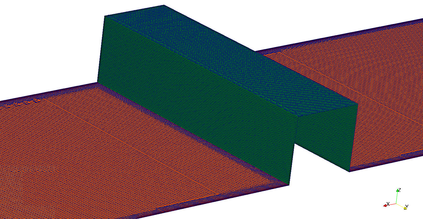
Figure 5:Resulting refinement for the Obstacle and Gravel-Bottom elements composing the mesh.
Once the feature and surface splitting process is complete, the cell removal process takes place. The latter requires one or more regions wrapped entirely by a bounding surface belonging to the domain. In order to specify the region in which the cells have to be kept, the locationInMesh keyword needs to be defined. This vector simply defines the region that wants to be retained.
locationInMesh (43.359 5 2.5803); // to decide which side of mesh to keep **Snapping
After having completed the cell splitting and cell removal processes, the Snapping process can take place. This task deals with moving the cell vertex points on the surface to create a conforming mesh, meaning to conform the input geometry. Here is a list of the keywords to be set:
nSmoothpatch: defines the number of smoothing iterations along the surface.
tolerance: specifies the region along the surface within which the points are attracted by the surface.
nSolverIter: defines the number of mesh displacement iterations.
nRelaxIter: defines the number of relaxation iterations during the snapping.
nFeatureSnapIter: defines the number of relaxation iterations used for snapping onto the features.
implicitFeatureSnap: if enabled, activates the implicit feature specification.
explicitFeatureSnap: if enabled, it snaps the mesh onto the features defined in the eMesh files.
multiRegionFeatureSnap: if also explicitFeatureSnap is enabled, the features between multiple surfaces will be captured.
// Settings for the snapping.
snapControls
{
    nSmoothPatch    3;
    // nSmoothInternal $nSmoothPatch;
    tolerance       1.0;
    nSolveIter      600;
    nRelaxIter      5;

    // Feature snapping

        nFeatureSnapIter 10; // default is 10
        implicitFeatureSnap false; // default is false - detects without doing surfaceFeatureExtract
        explicitFeatureSnap true; // default is true
        multiRegionFeatureSnap true; // default is false - detects features between multiple surfaces
}
Layering
In the case in which some irregular cells are present along the boundaries in the mesh obtained with the snapping stage, it is possible to introduce additional layers composed of hexahedral cells along the boundary. This stage includes shrinking the existing mesh in order to insert the layer of cells.
Users can choose between 4 different layer thickness parameters: expansionRatio, finalLayerThickness, firstLayerThickness, thickness. In this example case, specify only two to avoid an over-specification of the problem. The parameters to be set have the following meanings:
expansionRatio: necessary in order to calculate the relative size to the prescribed thickness of either first or final layer.
minThickness: indicates the minimum thickness of the layer.
featureAngle: represents the value above which the mesh is not extruded.
nRelaxIter: indicates the number of relaxation steps.
minMedialAxisAngle: indicates the minimum angle to select the medial axis points
For further details refer to the layer addition section of the OpenFOAM User Guide.
// Settings for the layer addition.

addLayersControls
//add the PATCH names from inside the STL file so STLpatchName-insideSTLName
 {
    relativeSizes false;
    layers
    {
    }

    expansionRatio 1.0;
    finalLayerThickness 0.3;
    minThickness 0.25;
    nGrow 0;

    // Advanced settings

    featureAngle 150;
    nRelaxIter 3;
    nSmoothSurfaceNormals 50;
    nSmoothNormals 3;
    nSmoothThickness 10;
    maxFaceThicknessRatio 0.5;
    maxThicknessToMedialRatio 0.3;
    minMedianAxisAngle 90;
    nBufferCellsNoExtrude 0;
    nLayerIter 50;
    NnRelaxedIter 20;
 }
Mesh Quality Controls
The final part of the snappyHexMeshDict file deals with the Mesh Quality. In this section, the values of the extrema encountered during the meshing process are defined. The purpose is to ensure an adequate quality of the resulting mesh. A comprehensive overview on the meaning of the mesh quality parameters can be found at https://
maxNonOrtho: maximum face non-orthogonality angle, calculated as the normalized dot product of the surface vector of a cell and the controid-to-centroid vector of two neighboring cells and .
maxBoundarySkewness: maximum boundary skewness.
maxInternalSkewness: maximum internal face skewness.
maxConcave: maximum cell concavity to check on the face of interior angles.
minVol: minimum cell pyramid volume, calculated as the dot product of the cell surface vector and the cell center to pyramid peak vector.
minArea: minimum face area.
minTetQuality: minimum tetrahedron quality, a small positive value to ensure cell checks run successfully.
minTwist: normalized dot product of the vector between two neighboring cell centers with their triangular face area vector.
minDeterminant: minimum cell determinant.
minFaceWeight: minimum face interpolation weight, calculated as the minimum of the projected distances between two neighboring cells and , notably
minVolRatio: ratio of the minimum and maximum of volumes of neighboring cells and ; that is, .
minTriangleTwist: the dot product of the unit normals of neighboring triangular elements.
nSmoothScale: smoothing iterations.
errorReduction: error reduction.
// Generic mesh quality settings

meshQualityControls
{
    maxNonOrtho 65;         // consider to set a limit of 45 deg
    maxBoundarySkewness 20;
    maxInternalSkewness 4;  // however, skewness should not exceed 0.5
    maxConcave 80;
    minVol 1e-13;
    minTetQuality 1e-15;
    minArea -1;
    minTwist 0.02;
    minDeterminant 0.001;
    minFaceWeight 0.05;
    minVolRatio 0.01;
    minTriangleTwist -1;

    // Advanced
    nSmoothScale 4;
    errorReduction 0.75;
}

debug 0;

mergeTolerance 1E-6;
Run Meshing (blockMesh)
Once the necessary keywords have been defined in the required dictionaries, the final step consists in running commands in the terminal in the following order:
Run the
blockMeshcommand to create the background mesh:
user@user123:~/OpenFOAM-9/channel/Mesh$ blockMeshRun the
surfaceFeaturescommand to create the .obj and .eMesh files from the initially imported STL files. These files are stored in the extendedFeatureEdgeMesh folder (channel/constant/extendedFeatureEdgeMesh).
user@user123:~/OpenFOAM-9/channel/Mesh$ surfaceFeaturesFor parallel runs, use the
decomposeParcommand to decompose the geometry into individual geometries for each MPI process.
user@user123:~/OpenFOAM-9/channel/Mesh$ decomposeParRun the
snappyHexMeshcommand to generate the mesh:For parallel runs (substitute “x” with the number of cores):
user@user123:~/OpenFOAM-9/channel/Mesh$ mpirun -np x snappyHexMesh -parallelAlternatively:
user@user123:~/OpenFOAM-9/channel/Mesh$ snappyHexMeshFor parallel runs, use the
reconstructParMeshcommand to reconstruct the geometry.
user@user123:~/OpenFOAM-9/channel/Mesh$ reconstructParMesh -constantFinally, the quality of the generated mesh can be analyzed by typing
checkMesh.
user@user123:~/OpenFOAM-9/channel/Mesh$ checkMeshA successful mesh generation returns the following (or similar):
  Checking topology...
    Boundary definition OK.
    Cell to face addressing OK.
    Point usage OK.
    Upper triangular ordering OK.
    Face vertices OK.
    Number of regions: 1 (OK).

  Checking patch topology for multiply connected surfaces...
                   Patch    Faces   Points                  Surface topology
                     Air    12879    13927  ok (non-closed singly connected)
          Concrete-sides   103621   109304  ok (non-closed singly connected)
           Gravel-bottom   132062   136819  ok (non-closed singly connected)
                   Inlet      288      339  ok (non-closed singly connected)
                Obstacle    27076    27416  ok (non-closed singly connected)
                  Outlet    20610    21252  ok (non-closed singly connected)

  Checking geometry...
    Overall domain bounding box (-2.5 -1e-06 -1) (56.7409 10 6.2461)
    Mesh has 3 geometric (non-empty/wedge) directions (1 1 1)
    Mesh has 3 solution (non-empty) directions (1 1 1)
    Boundary openness (-5.71676e-15 7.42351e-15 8.33816e-16) OK.
    Max cell openness = 4.76547e-16 OK.
    Max aspect ratio = 7.03771 OK.
    Minimum face area = 3.89097e-05. Maximum face area = 0.0910262.  Face area magnitudes OK.
    Min volume = 2.62118e-06. Max volume = 0.0180894.  Total volume = 2271.44.  Cell volumes OK.
    Mesh non-orthogonality Max: 47.7783 average: 6.72481
    Non-orthogonality check OK.
    Face pyramids OK.
    Max skewness = 3.12739 OK.
    Coupled point location match (average 0) OK.

  Mesh OK.

  End
The generated mesh can be visualized in ParaView by typing
paraFoamin the terminal.
user@user123:~/OpenFOAM-9/channel/Mesh$ paraFoamMesh Visualization
In order to visualize the generated mesh in ParaView, select the Apply option in the Properties section.
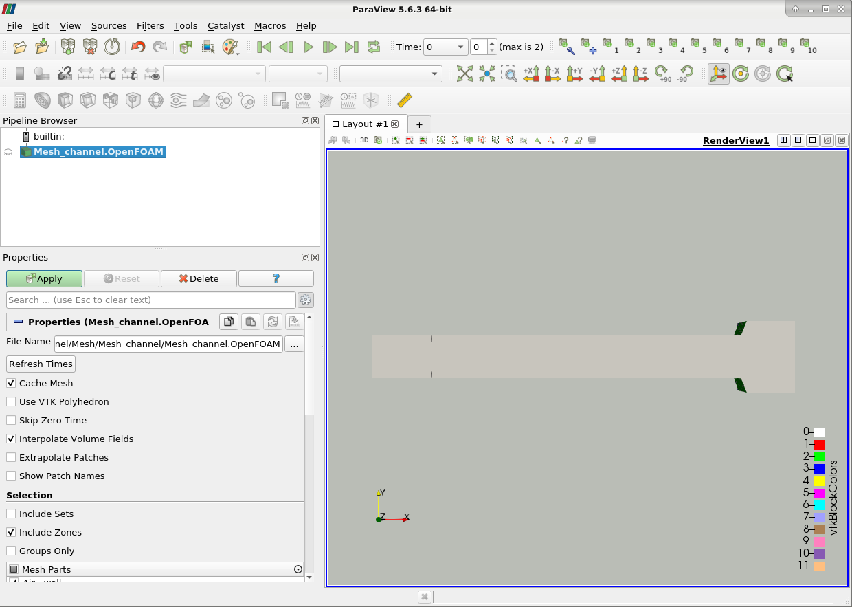
Figure 6:Visualization of the resulting mesh in ParaView.
The image below highlights some features required to adequately visualize the created mesh. Specifically, to analyze the cells, it is possible to select the option Surface with Edges. The various elements composing the mesh can then be selected/deselected to analyze specific parts in detail. Finally, in the case in which the Mesh Check returned errors, for instance, faces with high skewness, they can be visualized by selecting the Include Sets option.
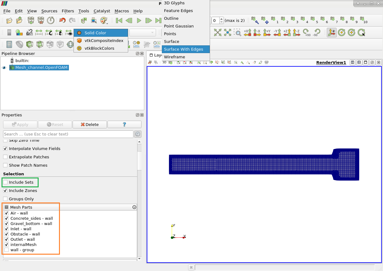
Figure 7:Visualization of the resulting mesh in ParaView, highlighting the created cells.