Since its early development, TELEMAC has become a robust and reliable tool for the numerically modeling of open surface flows. Yet there are a few little challenges and this always growing page provides some answers.
Recover crashed simulation files
When a Telemac run in parallel (using multiple cores) crashes, or if you need to recombine partial output files from each subdomain into a single file, Telemac’s postprocessing tools provide options for merging (or “stitching”) the submesh results. There are two main tools available:
GRETEL (the dedicated merging tool)
GRETEL takes the partial (subdomain) result files from each core and merges them back into a single SELAFIN/MED file for the entire domain.
This is generally the go‐to approach if your simulation crashed partway through, but you still want to visualize or analyze whatever partial results were saved.
PARTEL (in merge mode)
PARTEL is typically used to partition meshes for parallel runs, but it also has a merge capability. Some versions or workflows use PARTEL for both partitioning and merging.
However, for most modern Telemac configurations, GRETEL tends to be the more streamlined or default merging tool.
How to use GRETEL
If you ran your simulation in parallel and it crashed (or completed, but you just need to combine subdomains manually), locate the partial result files named something like:
T3DRES00000-00001.slf
T3DRES00000-00002.slf
…
or, for each subdomain, the corresponding files typically ending in
-0000X.slf.You can merge them by running GRETEL from the command line, for example:
runcode.py gretel -c <your_config> -f <your_config_file> --merge --ncsize <number_of_subdomains>Adjust the flags and file names as needed. If you were running Telemac3d use:
runcode.py telemac3d <steering_file> --merge -w <folder_path>Replace
<folder_path>with the directory that contains the output parts.
The exact syntax can vary depending on your version of Telemac. Some installations have a dedicated Python script or launcher for GRETEL.
Once GRETEL finishes, it outputs a single 3D SELAFIN (or MED) file with all subdomains reassembled. You can then visualize or continue processing that merged file in your preferred post‐processing environment (e.g., Blue Kenue, Paraview, QGIS).
Additional notes and tips
Checkpoint/Hotstart: If you need to restart a run from a particular time step, you can often use the partial subdomain files directly as a hotstart by setting the proper keywords in the steering file (e.g.,
RESTART FILE/RESTART = YES). In that case, you do not necessarily need to merge first: Telemac can read the subdomain files in a parallel restart.Partial Writes: If the run crashed mid-write or there was a file corruption, GRETEL (or PARTEL) might fail to merge. You would typically have to remove or fix the corrupted file(s) or restart from an earlier valid checkpoint.
Batch/Automatic Merge: In many Telemac scripts or workflows, merging happens automatically at the end of a simulation. If you need the merge to happen even if the simulation has crashed, running GRETEL or PARTEL in merge mode manually is usually the best solution.
Traceback errors
If a simulation crashes and it is not clear why debugging with the GNU Project debugger GDB is a good option. To do so, first install GDB:
sudo apt install gdbThen launch the steering file in debugging mode as follows:
telemac2d.py -w tmp simulation_file.cas --split
telemac2d.py -w tmp simulation_file.cas -x
cd tmp
gdb ./out_telemac2d
In gdb tap:
(gdb) runTo end gdb tap:
(gdb) quitThis approach also works with Telemac3d (and other modules).
Error Message Quickfixes
This section lists quick fixes for some frequent error messages.
- RANDOM CRASH
If TELEMAC crashes for apparently random reasons, make sure that:
No line in the steering file has more than 72 (active characteristics). For instance:
Too long line (bad)Correct line break (good)CLASSES CRITICAL SHEAR STRESS FOR MUD DEPOSITION = 0.011; 0.011; 0.011; 0.011CLASSES CRITICAL SHEAR STRESS FOR MUD DEPOSITION = 0.011; 0.011 ; 0.011; 0.011
Steering (CAS) Files
Prefer
:over=Place all model files in the same folder and only use file names without the directories of files.
Mesh File
Fine High-resolution Meshes
This section is co-authored by Federica Scolari.
For creating very fine meshes with a grid size smaller than 1.0 m, a selafin (*.slf) geometry file should be saved in double precision format (SERAFIND). Otherwise, model boundary edges may not be well represented in the computational mesh. Figure 1 illustrates the loss in boundary accuracy when single-precision (a) is used instead of double-precision (b).
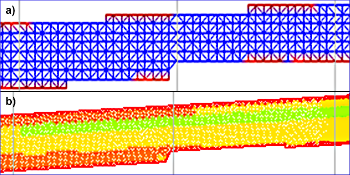
Figure 1:The loss boundary precision in a single-precision selafin mesh (a) compared to a double-precision selafin mesh (b).
Built-in Mesh Consistency Check
To verify if TELEMAC can read the mesh, load the TELEMAC environment (e.g., source pysource.openmpi.sh) and go to the directory where the mesh to be checked lives and run mdump, for example:
cd ~/telemac/studies/test-case/
mdump mesh-to-test.med
Until the time of writing this tutorial, mdump asks for input variables in French, which mean the following:
Mode d’affichage de noeuds? which means in
English: Node display mode?Option
1: Interlaced modeOption
2: Non-interlaced mode
Connectivité des éléments? which means in
English: Element connectivity?Option
1: NodalOption
2: Descending
Il y a 1 maillage(s) de type local dans ce fichier. Lequel voulez-vous lire (0 pour tous|1|2|3|...|n)? which means in
English: There is 1 local mesh(es) in this file. Which one do you want to read (0 for all or |1|2|3|...|n)?Option
0: Read allOption
i: Read mesh numberi
A standard answer combination of 1 - 1 - 0 will result in a console print of all nodes and connections between the nodes in the mesh, given that TELEMAC can read the mesh file. Starting with:
(**********************************************************)
(* INFORMATIONS GENERALES SUR LE MAILLAGE DE CALCUL N°01: *)
(**********************************************************)

- Nom du maillage : <<Mesh_Hn_1>>
- Dimension du maillage : 2
- Type du maillage : MED_NON_STRUCTURE
- Description associee au maillage :

(**********************************************************************************)
(* MAILLAGE DE CALCUL |Mesh_Hn_1| n°01 A L'ETAPE DE CALCUL (n°dt,n°it)=(-01,-01): *)
(**********************************************************************************)
- Nombre de noeuds : 243
- Nombre de mailles de type MED_SEG2 : 80
- Nombre de mailles de type MED_TRIA3 : 404
- Nombre de familles : 15

[...]
What this output means: If mdump can read the mesh, the mesh file itself is OK and potential calculation errors stem from other files such as the steering file or the boundary conditions. Otherwise, revise the mesh file and resolve any potential issue.
Boundaries
This section is co-authored by Federica Scolari.
No Water in the Model
Erroneous simulations where no water is entering or exiting the domain have most likely improperly defined boundary conditions. For instance, consider the open boundaries shown in Fig. 2 with prescribed Q (4 5 5) upstream and prescribed H (5 4 4) downstream.
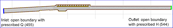
Figure 2:The definition of open (liquid) boundaries with prescribed Q (4 5 5) upstream and prescribed H (5 4 4) downstream.
Intuitively, you may think that the upstream boundary is number (1) and the downstream boundary is number (2). However, the order of boundary numbering depends on the definition order during the setup of the boundaries (e.g., described in the BlueKenue pre-processing tutorial). If you do not remember the definition order, it can be read in the boundary (*.cli) file at any time. For instance, the boundary file for the above-shown mesh (Fig. 2) looks like the representation in Fig. 3 where the Outlet is defined above the Inlet. Therefore, the downstream (Outlet) open boundary is number (1) and the upstream (Inlet) open boundary is number (2) in this simulation.
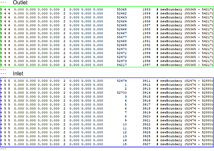
Figure 3:Exemplary definition of a downstream (Outlet) and an upstream (Inlet) open boundary in a boundary.cli file corresponding to Fig. 2.
Thus, these two boundaries must be referenced in the steering (*.cas) file as follows to prescribe a flow rate Q (e.g., 10 m/s) at the upstream and a depth H (e.g., 0.75 m) at the downstream boundary:
PRESCRIBED FLOWRATES : 0.;10
PRESCRIBED DEPTHS : 0.75;0.
Problem on Boundary Number (Simulation Stop)
This section guides through debugging error messages such as:
DEBIMP_2D: PROBLEM ON BOUNDARY NUMBER       2
        GIVE A VELOCITY PROFILE
        IN THE BOUNDARY CONDITIONS FILE
        OR CHECK THE WATER DEPTHS
        OTHER POSSIBLE CAUSE:
        SUPERCRITICAL ENTRANCE WITH FREE DEPTH
To get a better appreciation of the cause of the error (e.g., to figure out if supercritical flow conditions at the entrance are the cause), add the Froude number to the output variables in the steering (*.cas) file. To this end, add F to the output variable keyword:
VARIABLES FOR GRAPHIC PRINTOUTS : U,V,H,S,Q,FWith a more precise of the cause for the error, try one of the following options:
- Supercritical boundaries at the entrance
For supercritical flow conditions at the entrance, make sure that a
prescribed Q and Hboundary also gets a discharge and a depth assigned in the steering file. For instance, if the Inlet in Figures 2 and 3 was5 5 5(prescribed Q and H) instead of4 5 5, the steering file needs to prescribe flowrates and depths. For instance, add a depth of0.9for the Inlet as follows:PRESCRIBED FLOWRATES : 0.;10 PRESCRIBED DEPTHS : 0.75;0.9- Change the (vertical) velocity profile
The definition of a
VELOCITY PROFILEkeyword in the steering file is explained in the steady2d tutorial in this eBook. The additionVERTICALapplies to 3d models only (read more in the Telemac 3d (SLF) section).- 3d models with supercritical boundaries
Too many vertical layers may result in very thin 3d mesh elements that cause supercritical flows locally. Thus, consider reducing the NUMBER OF HORIZONTAL LEVELS in the steering file to satisfy the CFL condition.
Gaia (Morphodynamics)
UNKNOWN BOUNDARY CONDITIONS
TELEMAC-Gaia may interrupt with an error message such as KEYWORD: [...] UNKNOWN BOUNDARY CONDITIONS FILE .... This message means that the boundary condition type in the *.cli file does not match the boundary conditions defined in the *.cas file. For instance, if the tracer (suspended load) boundary column (9 in the Gaia *.cli file for CBOR) is set to 5, try using EQUILIBRIUM INFLOW CONCENTRATION : YES or double-check the numbers defined for the PRESCRIBED SUSPENDED SEDIMENTS CONCENTRATION VALUES keyword.
Read more about setting up boundary condition files for Gaia in the Gaia Basics section. The definition of boundary types in the Gaia steering file are described separately for bedload and suspended load.
BlueKenue
This section is co-authored by Federica Scolari.
BlueKenue may throw errors or not correctly show when working with 3d meshes. Some of the issues can be resolved by using the latest version of BlueKenue (v3.12.2-alpha at the time of editing this article).
- OnFileOpendata(): ERROR: on Activate()
Causes: The error message typically occurs with parallelized model runs when Telemac3d / PARTEL did not correctly merge the mesh at the end of the simulation.
Solution: Force TELEMAC to not delete the temporary simulation folder (a folder that is visible in the simulation directory by default only while a simulation is running). Keeping the temporary calculation directory is achieved through adding a
-tflag at the end of the simulation run command. For instance, tap the following to keep the simulation folder for a Telemac3d simulation (read more in in Annex A of the Telemac3d manual):telemac3d.py steering-file.cas -tThe temporary folder contains T3DRES (mesh partition) files that can be merged and then opened in BlueKenue. To merge the T3DRES files run the following command (make sure the TELEMAC environment is still activated with
source pysource.YOUR-ENV.sh):runcode.py --merge -w temp_directory/ telemac3d file.casTo get help with running this command, read this TELEMAC Forum entry.
For updates on this message, follow the BlueKenue thread in the TELEMAC Forum for troubleshooting updates on this error.
PostTelemac Plugin
Some versions of QGIS may throw a Python error (yellow frame in the top region of the map viewport) and a click on Stack reveals an error message. At the bottom of the error message, it might be written import error: no module named gdal. The error probably stems from an import statement in one of the PostTelemac plugin’s Python scripts. To troubleshoot the gdal import error, find the Python script that is raising the error message. For instance, the script posttelemac_hdf_parser.py may cause the error through its import gdal statement. To troubleshoot, open it, and on Windows, you may find it in the following directory:
C:\Users\USERNAME\AppData\Roaming\QGIS\QGIS3\profiles\default\python\plugins\PostTelemac\meshlayerparsers\posttelemac_hdf_parser.pyIn the opened file:
Open the concerned file, which is here:
posttelemac_hdf_parser.pyFind the
import gdalstatement and **replace it withfrom osgeo import gdal(i.e.,import gdalfrom osgeo import gdal)Save and close the Python file.
Retry to start the PostTelemac plugin. It should run without issues now.
SALOME-HYDRO
SALOME-HYDRO not starting (Kernel/Session)
If an error message is raised by Kernel/Session in the Naming Service, it will typically ends up in
$ [Errno 3] No such process ...
   RuntimeError: Process NUMBER for Kernel/Session not found
There are multiple possible origins of such errors that partially root in potentially hard-coded library versions of the installer. The following troubleshoot options exist but those require careful consideration as they might harm the operation system:
Manually create copies of newer libraries with names of older versions. For instance,
In the 4th line after running
./salome,Kernel/Sessionmay prompt
$ error while loading [...] libSOMETHING.so.20 cannot open [...] No such file or directoryIdentify the version installed with
whereis libSOMETHING.so.20(replacelibSOMETHING.so.20with the missing library); for example, this command may output
$ /usr/lib/x86_64-linux-gnu/libSOMETHING.so.40Create a copy of the newer library and rename the copy as needed by SALOME; for example, tap
sudo cp /usr/lib/x86_64-linux-gnu/libSOMETHING.so.40 usr/lib/x86_64-linux-gnu/libSOMETHING.so.20Most likely, the following files need to be copied:
sudo cp /usr/lib/x86_64-linux-gnu/libmpi.so.40 /usr/lib/x86_64-linux-gnu/libmpi.so.20
sudo cp /usr/lib/x86_64-linux-gnu/libicui18n.so.63 /usr/lib/x86_64-linux-gnu/libicui18n.so.57
sudo cp /usr/lib/x86_64-linux-gnu/libicuuc.so.63 /usr/lib/x86_64-linux-gnu/libicuuc.so.57
sudo cp /usr/lib/x86_64-linux-gnu/libicudata.so.63 /usr/lib/x86_64-linux-gnu/libicudata.so.57
sudo cp /usr/lib/x86_64-linux-gnu/libnetcdf.so.13 /usr/lib/x86_64-linux-gnu/libnetcdf.so.11
sudo cp /usr/lib/x86_64-linux-gnu/libmpi_usempif08.so.40 /usr/lib/x86_64-linux-gnu/libmpi_usempif08.so.20
sudo cp /usr/lib/x86_64-linux-gnu/libmpi_java.so.40 /usr/lib/x86_64-linux-gnu/libmpi_java.so.20
sudo cp /usr/lib/x86_64-linux-gnu/libmpi_cxx.so.40 /usr/lib/x86_64-linux-gnu/libmpi_cxx.so.20
sudo cp /usr/lib/x86_64-linux-gnu/libmpi_mpifh.so.40 /usr/lib/x86_64-linux-gnu/libmpi_mpifh.so.20
sudo cp /usr/lib/x86_64-linux-gnu/libmpi_usempi_ignore_tkr.so.40 /usr/lib/x86_64-linux-gnu/libmpi_usempi_ignore_tkr.so.20
Overwrite the SALOME-HYDRO’s internal version of Qt:
Copy
/usr/lib/x86_64-linux-gnu/libQtCore.so.5Paste in (confirm replacing
libQtCore.so.5)
/Salome-V2_2/prerequisites/Qt-591/lib/GUI/Qt5 support (GTK version compatibility)
With the newer versions of the Qt platform any menu entry in SALOME-HYDRO will not show up. To fix this issue, install and configure qt5ct styles:
sudo apt install qt5-style-plugins libnlopt0 qt5ctThen:
Configure
qt5ct(just tapqt5ctin Terminal)Go to the Appearance tab
Set Style to
gtk2and Standard dialogs toGTK2Click on Apply and OK
Open the file
~/.profile(e.g. use the file browser, go to theHomefolder and pressCTRL+Hto toggle viewing hidden files) and add at the very bottom of the file:
export QT_STYLE_OVERRIDE=gtk2
export QT_QPA_PLATFORMTHEME=qt5ct
Save and close
.profileand reboot (or just re-login).
Learn about Qt more at archlinux.org and in the arch wiki.