Acquire Aerial Drone Imagery
Collecting aerial imagery has become amazingly easy thanks to autopilot-controlled drones. Today, most drones come with programs for shooting aerial imagery and Structure-from-Motion (SfM)-based digital elevation models (DEMs). Since drone control is model-dependent (e.g., we use a dji Phantom 4 RTK drone for aerial surveys), this tutorial only describes basic settings for shooting aerial imagery and focuses on image processing to create DEMs.
Recommendations for survey flights with drones:
Use pre-defined terrestrial survey modes for sufficient overlapping
Preferably work with orthoimagery; only use 3d mode when strong winds are blowing
Account for approximately 20-30 minutes flight time per battery (approx. 2 hours recharging), which means that 8 batteries allow a smooth mapping
Ground control points may be omitted if RTK data is available, but we recommend using ground control points
In addition, an imagery-based DEM can also be built for shallow, clear waters (i.e., bathymetries) but other measurement techniques (e.g., Lidar or Sonar) are required for deeper waters (> 0.5 m water depth). Also, imagery-based bathymetry should be validated or corrected with local DGPS or total station measurements.
Metashape
The below figure shows the Metashape interface at program startup, ready for playing with drone imagery and SfM.
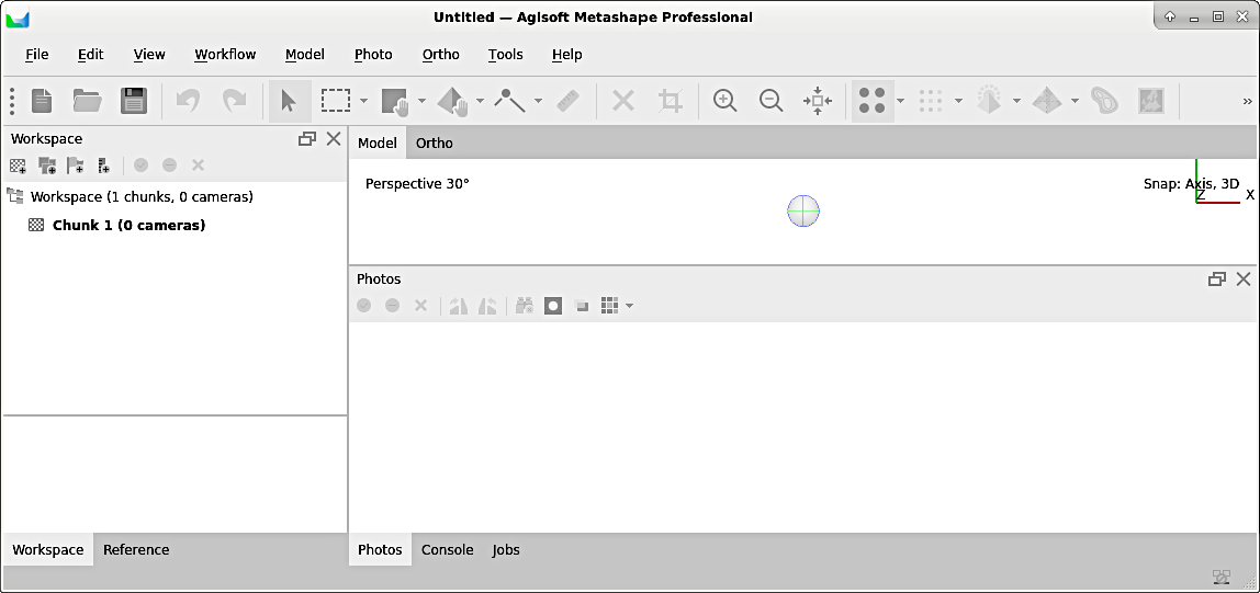
Figure 1:The initial Metashape interface.
Create a New Project
To get started, create a new project and save it (as .psx file) preferably one folder level above the images directory. Next, familiarize with the interface and explore the numerous workflows provided in the Workflow menu.
Load Images
Images may be loaded file-by-file, or much easier, from an entire directory. To add a directory (i.e., folder) containing aerial imagery from a single-camera drone, go to the Workflow menu > Add folder > Select folder containing images > Single cameras.
Align Images
When the drone flies over terrains, it sometimes needs to change its direction or position, but it always knows where it is (absolutely or relative to a ground station) if RTK-GPS data is available. As a result, the images may have been taken at different angles and different positions. To merge the images into one big picture of the terrain, the images need to be aligned by matching points that are visible on multiple images. The big picture can be created with Metashape’s alignment tool: go to Workflow > Align Fotos and consider the following settings in the popup window (see figure below) with the Advanced frame expanded:
Set the Accuracy to high for an acceptable equilibrium of resolution and computing time. Note that any additional increase in accuracy results in one order of magnitude longer computations times.
In Reference preselection select Source and make sure to use GPS data.
Advanced frame:
the Key point limit option enables defining characteristic points (i.e., points that the alignment algorithm can clearly identify on multiple images): make sure to enable identification of 10.000 to 40.000 characteristic points.
the Tie point limit defines a minimum number for tie points (i.e., points that the alignment algorithm identifies on two neighboring images): make sure to enable identification of at least 1.000 to 5.000 tie points.
use the enable exclusion of stationary points option, which makes sure that pixels that have the same (color) characteristics on all images (i.e., that are stationary) are excluded from the alignment identification. Thus, for instance, dirt spots on the camera lens will be excluded as alignment key points.
Enable adaptive camera fitting model for uncorrected camera distortion.
Leave all other default fields as-is and click on OK to start the alignment. Depending on the quantity and size of images as well as the calculation capacity of your computer, the alignment takes 5-30 minutes.
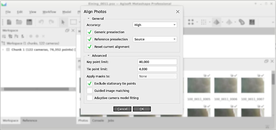
Figure 2:The align fotos popup window in Metashape.
When the alignment is accomplished, produce a coarse point cloud (select from the Tools menu). A qualitatively good coarse point cloud is characterized by at least 100 tie points per m or more than 50.000 tie points per 100 images (with a resolution of 4605x3227). In addition, verify errors with a click on the Reference ribbon (typically at the bottom left of the Metashape window). The longitude/latitude error should be 2 cm.
Build Dense Point Cloud
When the quality is sufficient and the error is acceptably low, proceed with building a dense point cloud (select from the Workflow menu). In the dense point cloud popup window (see also figure below), make the following settings:
Set the quality to high
Choose depth filling as a function of vegetation density:
if no to very little vegetation, select moderate / agressive
if vegetation is present, a good performance (point cloud quality vs. computing time) can be achieved by choosing the mild option
in the case of very dense vegetation, depth filling may be deactivated though this can lead to very long computing times
Click OK to create the dense point cloud (may take again 5-30 minutes)
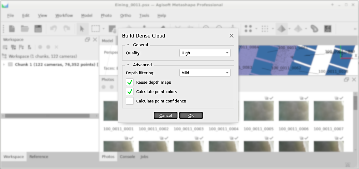
Figure 3:The dense point cloud popup dialogue in Metashape.
The quality of the dense point cloud can be considered good if the process found:
At least 20 to 30 neighbors.
Approximately 10 million points per 100 images (with a resolution of 4605x3227).
Create DEM
The dense or coarse point cloud can be used with many other workflows and the creation of a DEM is only one option. To create a DEM, go to Workflow > Build DEM and consider the following aspects in the build DEM popup window (see figure below):
Projection:
use a geographic type for projection onto a GeoTIFF raster, which is compatible with most GIS software, such as QGIS.
Metashape’s default projection is
EPSG:4326(read more in the section on projections in this eBook), which corresponds to the projection commonly used with aerial imagery interfaces (e.g., GoogleEarth).
Source data:
the tie points option leads to the lowest resolution.
the depth maps option is a good compromise between resolution and computing time.
the dense cloud option leads to the best quality but also a very long computing time.
Advanced frame: keep automatically proposed values to ensure consistency.
The OK button launches the DEM creation, which may take again 5-30 minutes.
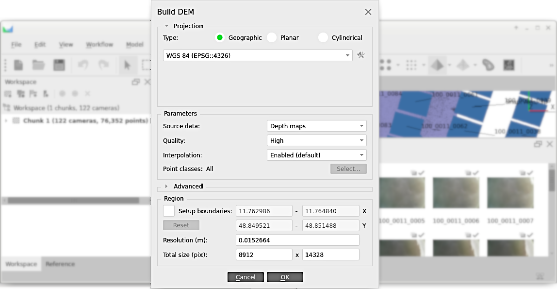
Figure 4:The DEM creation popup dialogue in Metashape.
Finally, export the DEM with a right-click on the DEM in the Workspace (if the DEM is not visible, expand the Chunk 1 entry - or whatever name it has - in the Workspace) and select Export DEM.... We recommend to save the DEM in GeoTIFF (.tif) format, which is compatible with QGIS. If .tif was selected, a popup window for exporting the DEM opens. In the popup window, check the export world file option and keep all other defaults (optionally, create a .kml file for working with GoogleEarth). The world file will be important for QGIS (and any other GIS software) to know where the DEM is geographically located with respect to the selected projection.
Create a Mesh
Similar to the DEM workflow, Metashape provides a workflow for creating a mesh (Workflow > Build Mesh) in the form of a triangulated irregular network (TIN). The Source data options are similar to the ones in the DEM workflow, with an additional option of using the DEM for meshing. Also for a mesh, High quality and face counts result in the best representation of the terrain and high computing costs. If the goal of the mesh generation is its usage with a numerical model, lower quality and face counts might be a good choice to keep the time for running the numerical model low. The mesh generation takes again 5-30 minutes.
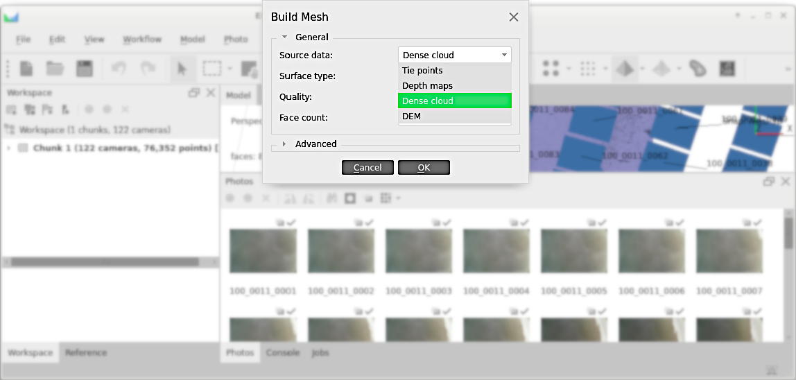
Figure 5:The mesh creation popup dialogue in Metashape.
Once the mesh creation is finished, it can be exported with a right-click on the 3D Model entry in the Workspace and a left-click on Export Model.... If the 3D Model is not visible in the Workspace, expand the Chunk 1 entry (or whatever name it has). For use with a numerical model (e.g., OpenFOAM), the STL (.stl) format is a good choice.